Video links:
See the C-2 in action in the videos listed below:Original release (MFFK & ICE Tech)
Tutorial videos:
See the C-2 in action in the videos listed below:Tutorial 1: Cockpit familiarization and instruments
Tutorial 2: Takeoff and One-Speed approaches ashore
Tutorial 3: Carrier Operations
Features:
- realistic flight model
- smooth handling
- dynamic flight controls
- digital PFD & dash instruments
- integrated SA GPS/transponder
- compatible with SA KellyFuel pump v3.1
- compatible with AMOK catapults and arrestor cables (carrier capable)
- parachute jump lights
Version 1.1 additions:
- Flight Engine has been reworked (heavier stick)
- GTFO! ready
- Easy Cargo/Passenger conversion option added
- Arrestor Cables/Carrier Module added for Field Carrier Landing Practice (FCLP)
- N-Numbers are now automatically assigned (manual registration option still available)
- Fixed minor issue with cargo crate unloading
- Fixed minor issue with ramp ladder positions
Version 1.0 includes:
- GPU, Air Starter Unit and APU autonomy
- 2 cockpit + 3 passenger seats
- cargo system
- N-numbers
- failures
Contents
- General Notes
- Systems/Avionics
- Approach Indexer
- GPU and APU
- Fueling
- Cargo system & GTFO!
- Annunciator panel & Failures
- Flight Characteristics & Notes
- Normal Operations
- Carrier Operations
- Emergency Procedures
- Chat Commands
- Acknowledgements
General Notes
Rudder control: In both Mouselook and External view, Rudder is controlled by clicking and holding the left mouse button, together with left/right stick input (arrow keys or a/d). In external view, Shift + left/right input controls rudder as well.
Stalls/spins: The aircraft is capable of simulating stalls and spins. In case of low RPM or engine failure, the autofeather system will activate. This will reduce drag and enable the aircraft to glide for an emergency landing (see relevant section below).
Mouselook flight: The C-2 was designed to be flown in Mouselook using the Primary Flight Display (PFD).
Checklists: Use the provided checklists to become familiar with normal procedures.
Paints/Decals: Decals allow the easy change of squadron markings and tail numbers. The main fuselage may be repainted.
Linking/Unlinking: The C-2 is modifiable and additional links may be added, however some caution is required. Please do NOT rescale the aircraft, NOR modify the names or description fields of existing links, or it will break. Do NOT remove any existing links. Make sure any additional links you add have unique names, different to the ones of already present links. To do so safely, right-click the aircraft and set all scripts to "no-run". Proceed with (un)linking, making sure not to change the root prim. When you are done, edit the C-2 and set scripts to run, from the pie menu. Then finally, reset all scripts.
Systems/Avionics
We begin with an overview of the left seat pilot's instruments, including the PFD.
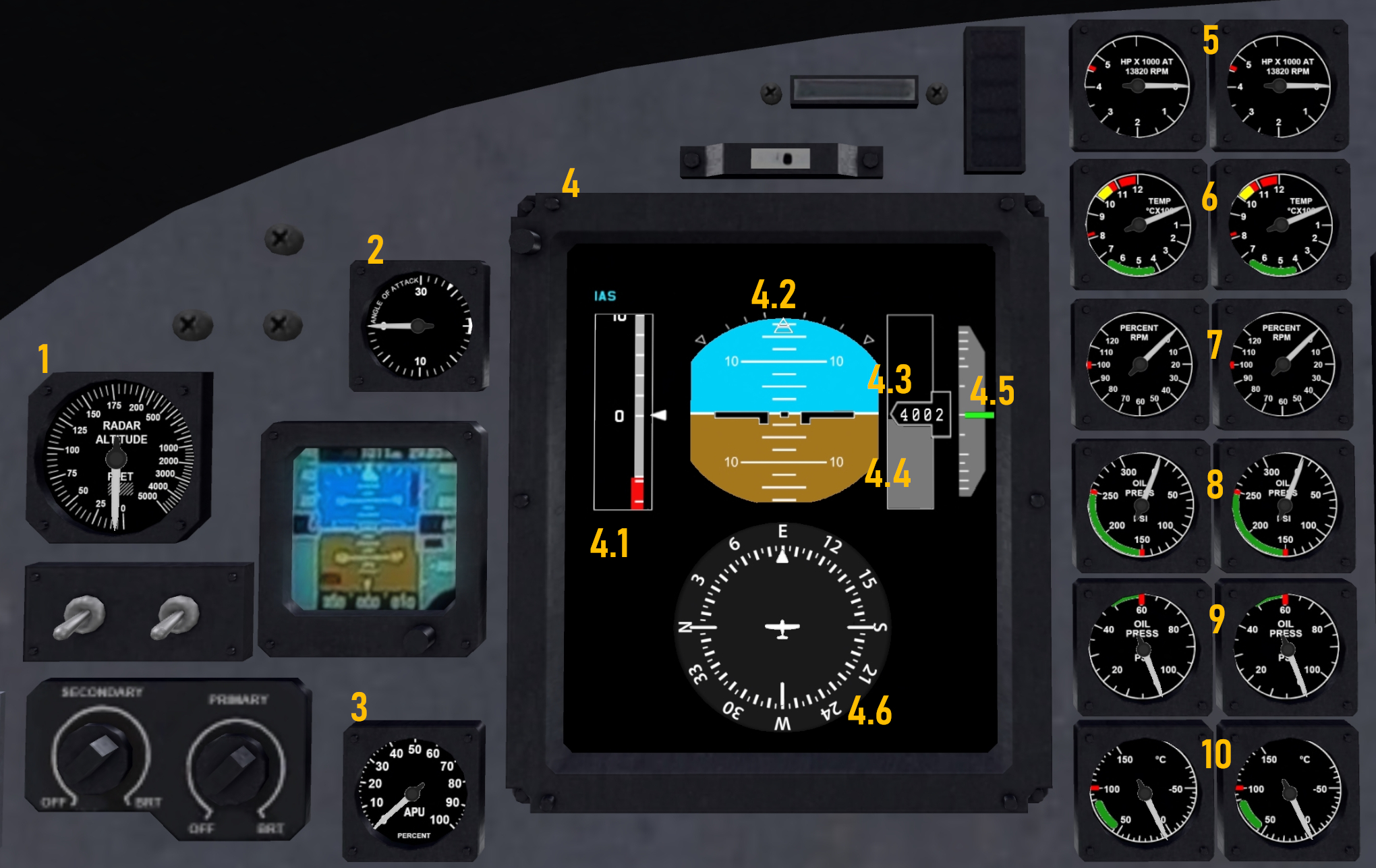
-
Radar altitude in feet. This is the distance below the aircraft until the first obstacle is encountered. (SL land, SL water, or other rezzed objects)
-
Angle Of Attack (AOA) indicator. Measures the angle between the longitudinal axis of the aircraft and the relative wind in scaled units 0-30. Optimal AOA in landing configuration is 20 units (needle should be inside the white band in the 3 o'clock position). Important: The dial scaling is relative to the optimal position. It does not measure AOA in degrees.
-
Auxiliary Power Unit (APU) RPMs. The APU generator provides AC electrical power as well as limited hydraulic power. Also provides aircraft autonomy, but draws fuel from both tanks.
-
Primary Flight Display (PFD). Provides the following flight information: Indicated Airspeed (IAS) in knots (4.1), Attitude and Roll indicators (4.2), digital SL Altitude in meters (4.3), visual Radar Altitude queue as the gray tape in (4.4), Vertical Speed indicator (4.5), Compass (4.6)
-
Torque indicator in HorsePower (HP) units. The readings are accurate only when the engine is operating at 100% RPMs.
-
Turbine Measured Temperature (TMT) indicator. Yellow band indicates hazardous area and is accompanied by "OVHT" (overheat) warning light. Operating the engine in the area marked with the red band can cause engine failure. TMT may exceed limits during engine start (for up to 15 seconds), then reduce back to the green area of the gauge. If the engine was previously running, allow time for TMT to drop to zero, before starting the engine. Failure to do so may result in a "hot start" and lead to engine damage.
-
Propeller RPM.
-
Gearbox Oil Pressure.
-
Power Section Oil Pressure.
-
Oil Temperature.
Moving on the main/center panel:
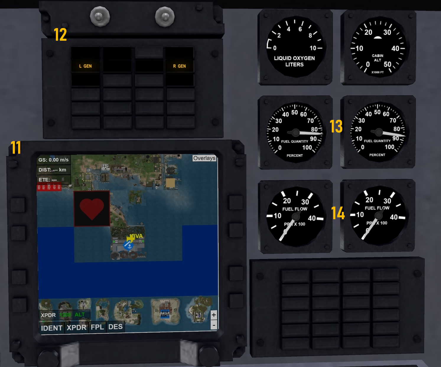
-
GPS/Transponder, powered by Shergood. More information on its operation can be found in the Shergood webpage.
-
Warning lights.
-
Fuel quantity percentage (%). Each tank takes 912 gallons of JP-5 fuel (simulated as "JPA" in the KellyFuel pump).
-
Fuel flow in hundreds of pounds per minute (rescaled for the SL simulation).
We now turn to the right-seat pilot instruments and PFD.
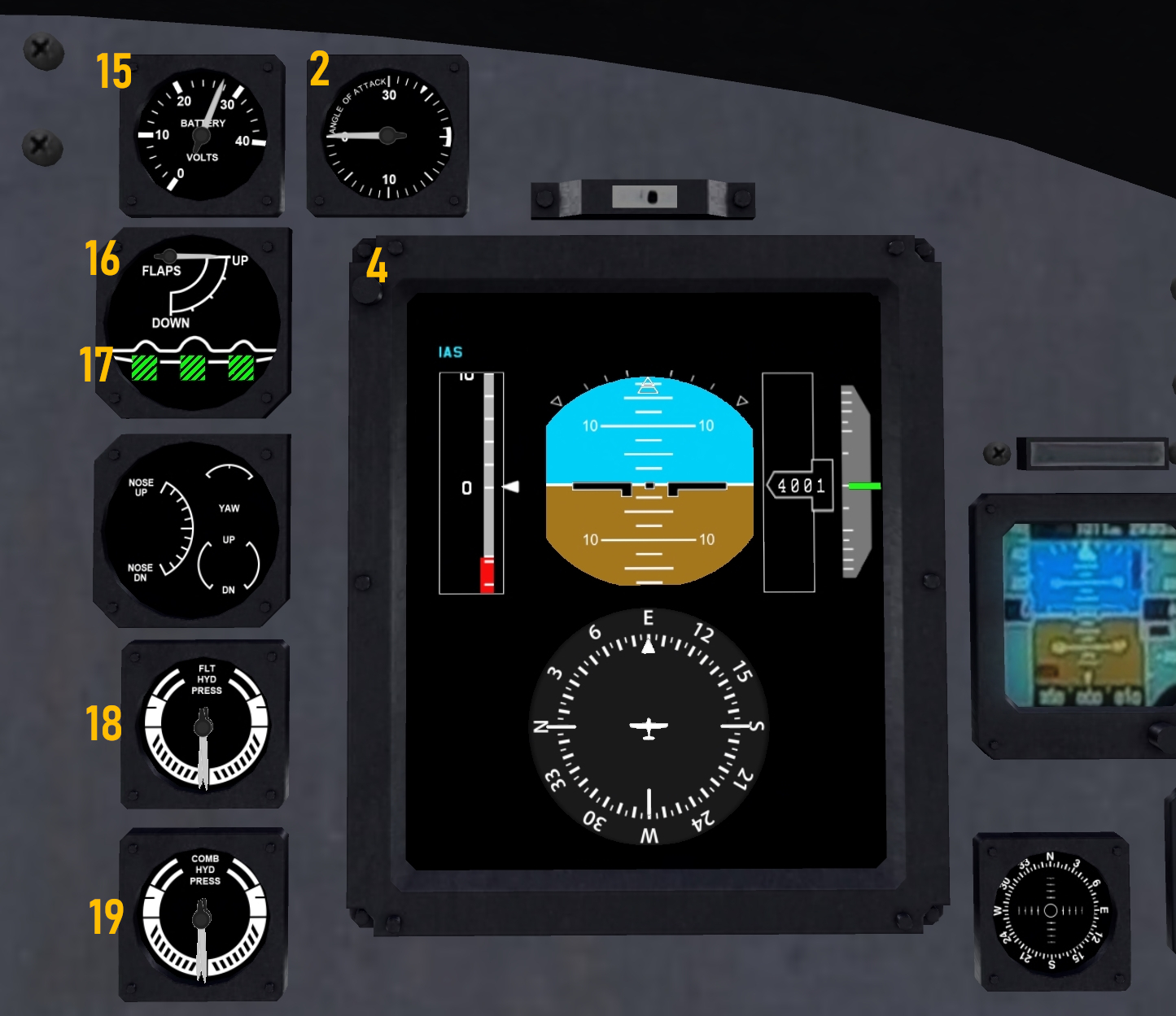
-
DC Battery (volts). At least 27V required for the engine starter. The battery bleeds out (faster or slower depending on what you turn on). If it drops below 20V, external power or APU is necessary to power the avionics.
-
Flaps position indicator (0, 10, 20, 30 degrees).
-
Landing Gear status indicator. Green color indicates gear is down and locked. Red color indicates landing gear system in motion. White color indicates gear is up.
-
Flight Hydraulic pressure. The Flight Hydraulic system provides pressure to the primary flight controls.
-
Combined Hydraulic pressure. The Combined Hydraulic system provides fluid pressure to remaining subsystems (landing gear, ramp, flaps, wing fold, arresting hook).
Approach Indexer
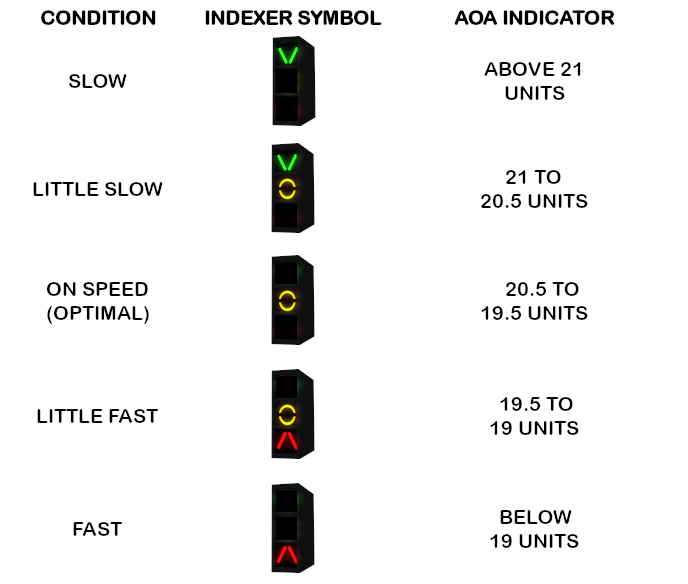
The Approach Indexer lights are located on the glareshield, with a separate device for the left and the right seat pilot. The Indexer lights are an indispensable tool for visually maintaining on-speed AOA approaches. The legend below identifies the Indexer symbology and its correspondence to the AOA indicator.
GPU & APU
The C-2 engines require both electric power as well as air pressure in order to start. This is accomplished with the help of either the Ground Power Unit & Air Start Unit combo, or (for complete autonomy) of the Auxiliary Power Unit (APU). Both options are described below.
-
GPU & Air Start: Provided the aircraft is on the ground with brakes set, the chat command gpu will position and connect the NC-10 Mobile Electric Power Plant as well as the MSU-200 NAV Air Start Unit. The first provides 28V of DC voltage to the essential bus and charge the battery. The second is an external air compressor connected directly to engine 2 for air/pneumatic start. This option does not use fuel from either tank, but the 28V DC voltage does not power the (AC) hydraulic pumps either. At least one engine must be started before the combined hydraulic pressure system can operate the ramp, flaps, or the wing folding mechanism.
-
APU: The Auxiliary Power Unit provides 115V AC voltage which is transformed into 28V DC voltage to power avionics, charge the battery. It also powers the hydraulic pumps, and therefore provides hydraulic power for ground operations, allowing the movement of the ramp, flaps, and wings. This gives the aircraft autonomy, at the cost of the APU engine using fuel from both tanks. The APU speed (RPMs) can be monitored by the gauge to the bottom left of the left-seat PFD. APU start/stop is toggled by the chat command apu.
Fueling
The C-2 currently supports 2 options for fueling:
-
Simple refuling by the chat command "refuel". This will top both tanks. Ensure the aircraft engines are off first.
-
Using SA "KellyFuel" pump v3.1. Park the aircraft close to the pump, engines off. Click the pump to detect the aircraft. Be sure to ground the aircraft first! Select the tank, attach the pump (JPA) and follow the instructions on the pump screen. More information on the KellyFuel pump can be found in the Shergood webpage.
Cargo system & GTFO!
The C-2 comes with a simple and fun system that allows avatars to load and unload a number of premade cargo crates. This feature requires you to be at a location which allows rezzing.
-
Rez the "Cargo Crates Box" and unpack the crates into your inventory.
-
There are 8 different crates named Cargo_0, Cargo_1, ..., Cargo_7. They come with Copy+Transfer permissions, so you can even pass them to your friends.
-
Any number of different crates (up to 8 in total) can be loaded on the C-2, but each crate number cannot be loaded more than once. For example, if Cargo_3 has already been loaded, it cannot be loaded a second time.
-
Rez the crates you want to load on the ground outside the aircraft, open the ramp and click the boarding ladders stowed on the aft left side of the fuselage to deploy them.
-
Walk next to the crate you wish to load and left click it. An "attach" permission message will pop up. Grant the permission and your avatar will pick up the crate. You can now move with the crate in your hands by simply walking.
-
Carry the crate you are holding inside the aircraft and left click on the crate in your hands again. It will be loaded in the aircraft and appear in the cargo area of the C-2. Repeat with the rest of the crates you wish to load.
-
To unload a crate, walk to the cargo area of the aircraft, zoom in and hover the mouse on the crate you wish to unload and left click. The crate will be pulled out of the stack and an "attach" permission message will pop up. Grant the permissions and the crate will appear in your hands. You may now walk out of the aircraft.
-
With the cargo crate in your hands (and at least 10 meters away from the C-2), left click the crate again, and it will be placed on the ground in front of you.
-
If you are far away from the C-2, you may pick up a crate and carry it to a spot of your choice, then click it again to drop it on the ground. Any other avatar may click on your crate on the ground and pick it up to move it. This can be used for RP purposes to have several people working together to load and unload the aircraft. Note, however, that a given crate can only be picked up and moved up to three times (afterwards, a new one has to be rezzed).
As of v1.1, the C-2 is GTFO! ready. You can add your own cargo links, as follows:
-
Rez a fresh C-2 from your inventory, sit on the pilot seat and type cargo to remove the passenger seats and bring the C-2 to its cargo configuration.
-
Stand up from the C-2, and stop all scripts. To do this, right click on the aircraft to bring up the pie menu and choose: "More > More > Scripts > Stop Scripts".
-
Rez your favorite cargo crates, edit them, position and resize them as required, so that they fit inside the cabin.
-
Edit and rename your (still unlinked) cargo crates CARGO!1, CARGO!2 and so on.
-
Select all your (renamed) cargo crates and link them to the C-2. When linking, make sure to select the C-2 last, so that the root prim remains unchanged!
-
Using the "Edit Linked" option of the Edit Window, edit each one of your (linked) cargo crates, go to the "Features" tab, and set the "Physics Shape Type" of your crates to "None".
-
Right click on the full C-2 (not individual links) using the pie menu, and reset all scripts by choosing: "More > More > Scripts > Reset Scripts".
-
Now set all scripts to run, by right clicking on the C-2 using the pie menu and choose: "More > More > Scripts > Run Scripts".
Your cargo crates will start to become visible when loading a GTFO! job, and will become invisible when you are unloading. For information on how to configure the GTFO! notecard, see the GTFO! webpage
Warning lights & Failures
The C-2 warning panel contains nine warning lights, as shown in the legend below:
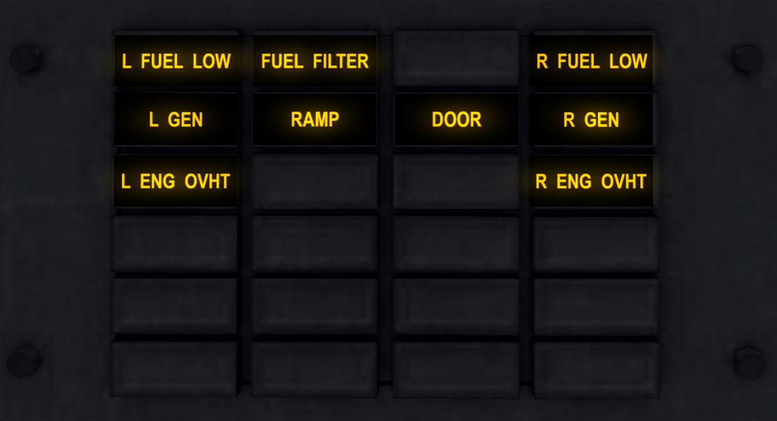
L/R FUEL LO: The left/right fuel tank has less than 10% fuel left.
FUEL FILTER: Will illuminate if the fuel tank is filled with the wrong fuel type. If so, land as soon as possible and inspect/repair the aircraft once on the ground. A failure in the fuel pump may lead to engine failure.
L/R GEN: The left/right generator is not currently providing AC electric power. If the GPU or APU are not running then the battery provides DC power. This light should be extinguished in normal engine operation.
RAMP: Illuminates if the aft ramp is open.
DOOR: Illuminates if the crew door (left side) is open.
L/R ENG OVHT: If TMT exceeds limits for extended time intervals, the engine overheat light will illuminate. Reduce power (and TMT) immediately. If the overheat light does not extinguish soon after TMT reduction, land as soon as possible for engine inspection and repairs. If the engine overheat light remains illuminated, or if TMT continues to exceed operational limits, the engine may fail during flight.
Flight Characteristics & Notes
Aircraft weight due to fuel is not yet simulated in v1. Aircraft weight due to seated avatars is always simulated.
The aircraft stalls by angle-of-attack (AOA). The critical value is between 15-18 degrees. Stall speed (V_s) in landing configuration (full flaps) is 22 knots.
VR (Rotation airspeed) is approximately 30 knots with 10 degrees of flaps extended. Monitor airspeed during your takeoff roll and rotate (gently pull back on the stick) as soon as airspeed exceeds 30 knots.
VREF (reference airspeed for final approach with full flaps) is approximately 26 knots.
Flaps are high lift devices: they increase lift (and add some drag). Gear extension increases the drag as well. You will see a noticeable effect on airspeed.
Rolling the aircraft causes the lift vector to deviate from the vertical direction and no longer fully balances the aircraft weight. This may result in loss of altitude. The effect may appear more noticeable at lower airspeeds. Consider slight upwards pitch during banked turns, as required.
The aircraft is not a trainer and is NOT certified for aerobatics. Avoid excessive banking (more than 60 degree rolls), steep dives or climbs. Voluntary spins are not authorized in this aircraft.
A pre-stall buffet warning horn will sound in the form of a series of repeated short "pulses", whenever a stall is imminent. Take swift action to lower the nose and reduce the AOA, in order to avoid the stall.
In case of stall, the stall horn (continuous sound) will sound. To recover, push the stick forward (i.e. down pitch). Your goal is to bring the nose to align with velocity (more precisely, to reduce AOA). Throttle up and stabilize the aircraft to wings level. Do NOT practice stalls at low altitude.
The aircraft can enter a spin by rudder input during a stall. Throttle down to idle. Wait for the nose to drop below the horizon. Apply opposite rudder to the direction of the spin, then add power and stabilize the aircraft to wings level. The ability to recover from an involuntary spin highly depends on the initial altitude.
Sometimes lag during sim crossings requires avatars to stand and resit. The toggle command ph has been added to turn the aircraft physical/unphysical.
Normal Operations (Ashore)
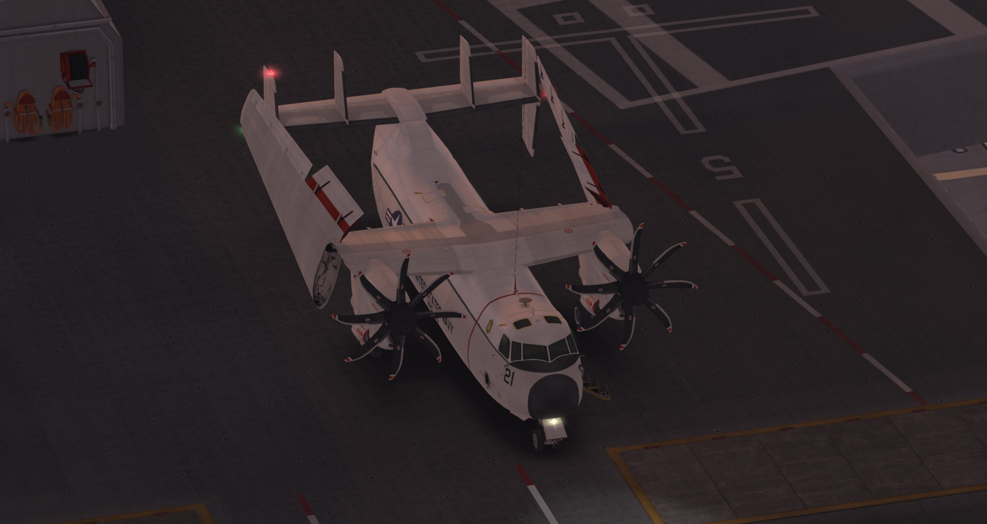
In addition to the following notes, use the checklist to ensure proper aircraft configuration for the various stages of flight.
Normal Takeoff
Check your lineup using the PFD compass. Check flaps extended (as required). Check all warning lights extinguished. Set the brakes.
Set takeoff power to 90-100% throttle. Release the brakes. Monitor airspeed and rotate at or above 30 knots. Gently raise the nose to +5 degrees pitch, then gradually to around +10 or +15 degrees pitch.
Upon establishing a positive rate of climb raise the landing gear. Retract flaps above 35 knots. Set climb power to around 70%. Monitor airspeed and adjust pitch and throttle accordingly.
Upon reaching cruise altitude set cruise power around 60-65%.
Normal Approach (Visual, Straight-in, Constant AOA)
It is possible to fly the final approach with the nose slightly below the horizon and flare it (raise the nose above the horizon just prior to touch down), so that the main gear touches down first. However, this is not the standard approach procedure for the C-2. Instead, the C-2 flies on-speed approaches (or, constant AOA approaches). The procedure is described here.
Start at throttle 55%, wings level, gear down, flaps extended 30 degrees, at an initial altitude of 30 meters AGL (above runway elevation). Nose initially on the horizon and vertical speed zero (maintaining altitude).
Line up early. At a distance of 1.5 sims from the runway, power down to 50%. The aircraft will slow down and have the tendency to descend. To prevent this, gently raise the nose just slightly (do not exceed 5 degrees above the horizon) maintain altitude. Do NOT raise the nose abruptly or too high, or you will stall the aircraft.
One sim before the runway, enter the glide path (i.e. start descent on final approach). To do this, reduce throttle gradually to 45% and then 40% (as required). The nose of the aircraft should be around 2.5 to 5 degrees pitch up (above the horizon). Note that the aircraft nose will have the tendency to drop, so correct this by briefly tapping the "S" (or Down Arrow) key, to maintain the nose above the horizon. Your airspeed should stabilize at around 25-26 knots. Excessive positive pitch will increase your AOA, and might stall the aircraft, so monitor the Approach Indexer lights to stay "on speed". You are aiming for the amber "cicle" light. Ideally, you want to establish a stabilized approach (constant pitch, constant power setting, constant airspeed, constant AOA).
In this configuration, throttle primarily controls your descent rate, while pitch (up/down nose) controls your airspeed.
The optimal glideslope for this aircraft is around 6-7 degrees. If you start too high, you will not be able to lose the excess altitude easily (you would have to reduce power to 30% and let the nose drop below the horizon for a bit). If you are too shallow, add power to reduce your descent rate. High and fast is better than low and slow. If you think you aren't coming in correctly for the approach, wave off and try it again. Being at the right initial approach altitude, controlling your airspeed and your pitch angle are the key.
If you are correctly stabilized for approach, you should NOT need to reduce nor cut power for landing (that is, if your airspeed on final approach is stable at around 26 knots). If you drop power below 40% under those conditions will result in a significant loss of altitude (and if you pull up suddenly or too hard/too much, you might stall it as well). If you are at the correct airspeed but too high, let the nose drop to the horizon (or even below it, momentarily) and drop power slightly and only for as long as needed to increase your descent rate. Then, power back to 40% and bring the nose back between 2.5 to 5 degrees above the horizon. If you are below glideslope, add power and adjust as needed. If you are descending too fast, reduce power and slightly lift the nose. If you are too too slow, add power slightly and slightly lower the nose. Overall, aim to be around 40-45% power during final (ideally 40%).
Only minor pitch corrections (tapping the "S" or DownArrow key periodically) are needed in order to keep the constant AOA ("amber circle light"). If all goes well you will reach the runway threshold at a height of about 10 feet (~3 meters). Normally, this aircraft requires no flare and should just touch down on its own with the main gear first. If you need to make a "smoother" landing, you can slightly add power to 45% just before touchdown. Adding too much power may balloon the aircraft and lead to a long landing, so avoid adding extra power just prior to touchdown if your airspeed is more than 30 knots.
Avoid nose first landings. Obviously :)
Carrier Operations
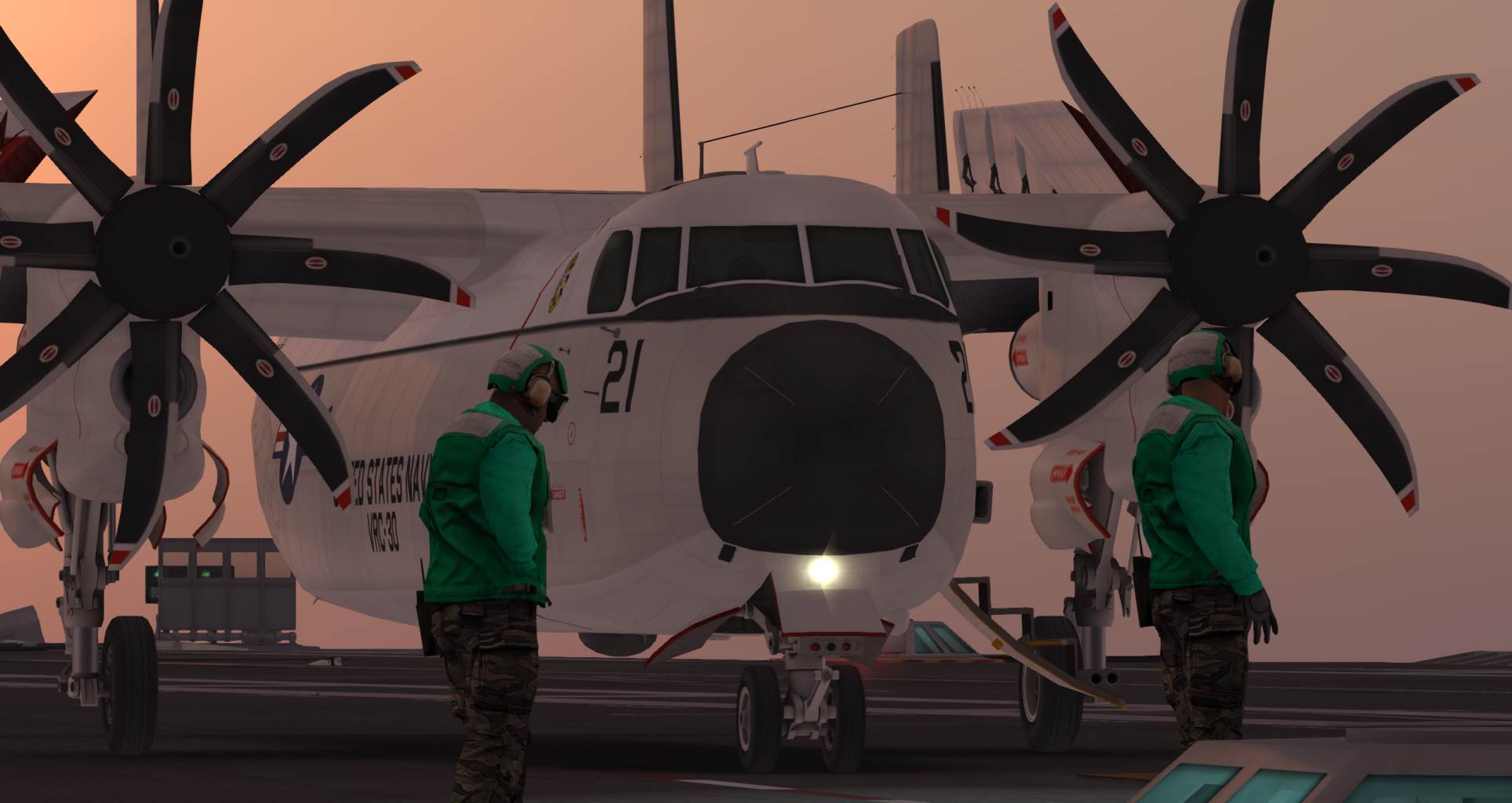
This is where things get interesting!
The C-2 is an aircraft made for COD (Carrier Onboard Delivery), meaning the transport of supplies and personnel to and from aircraft carriers.
Carrier Launch
This will work on any carrier or launch platform equipped with AMOK compatible catapults.
Position the C-2 so its towbar is directly over the shuttle.
Check your lineup. Check that the wings are unfolded. Extend flaps to 10 degrees. Check all warning lights extinguished. Set the brakes.
Initiate the launch sequence from the catapult (on MFFK carriers, click the bubble next to the catapult). A message in local chat saying "Preparing to launch" will confirm that the sequence has initiated.
The launch is automatic (no need to set takeoff power nor release brakes). Keep hands off the controls until you are clear of the deck.
Once you are clear of the deck, gently raise the nose to gradually start your climb and execute a small clearance turn.
Upon establishing a positive rate of climb raise the landing gear. Retract flaps above 35 knots. Set climb power to around 70%. Monitor airspeed and adjust pitch and throttle accordingly.
Upon reaching cruise altitude set cruise power around 60-65%.
Carrier Recovery
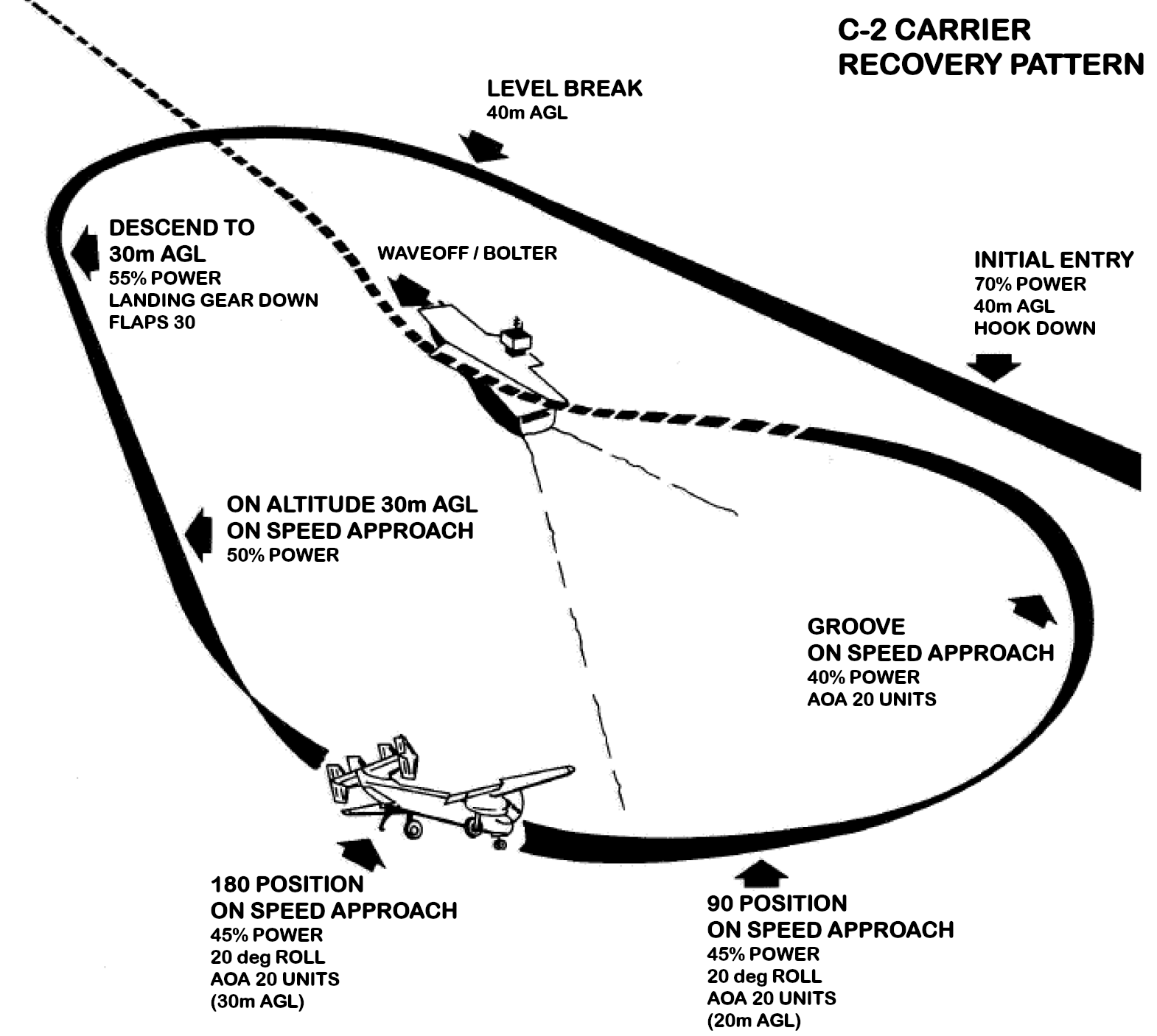
The Navy uses a portside (left-handed) landing pattern for carrier recoveries. The procedure for the C-2 simulation in SL is outlined below.
Important: all AGL altitudes for this procedure refer to heights above the flight deck level of the carrier! In MFFK carriers, the flight deck is at ~40 meters elevation.
INITIAL ENTRY: Overfly the carrier (slightly displaced to its right) at 70% power or more, hook extended at an altitude 40m AGL (above deck level). Verify the landing deck is clear.
BREAK: Either half-way inside the carrier sim, or preferably half-way inside the next sim, execute a left break maneuver as follows: apply left roll (~30-45 degrees), and make any necessary pitch adjustments to maintain altitude. The goal is to fly a half-circle arc, gradually powering down to 50-55% during the turn. You will have to gradually ease the turn by reducing the roll angle, so that you end up flying the reciprocal heading.
DESCEND TO 30m AGL: Upon exiting the break, extend full flaps (30 deg) and lower the landing gear. You should be flying at 50-55% power and descend to 30m AGL.
ON ALTITUDE 30m AGL: At the abeam position (carrier's stern across your left wing), you should be on altitude (30m AGL), at 50% power and fully configured. The aircraft may have the tendency to descend, so slight nose up attitude is required to maintain altitude.
180 POSITION: Half-way inside the approach sim (behind the carrier), reduce power to 45%, roll the aircraft left by ~20 degrees, and pitch the nose up to remain "on speed" (in other words, maintain 15 units AOA). For the last part, instead of looking at the AOA gauge, use the AOA indicator lights and pitch the nose up until the amber circle illuminates. The goal here is to turn while descending and while remaining on-speed. Do NOT look at the carrier at this stage. Fly the procedure as described instead.
90 POSITION: At this position, 90 degrees of turn remain until lineup. Continue the turn at 45% power, 15-20 degrees of roll, and stay on-speed (amber circle light on the Approach Indexer). In Mouselook view, you may now slightly turn your camera angle (using the mouse), and take a quick peek at the carrier so you can adjust and ease your turn accordingly. Remember to return to forward Mouselook view afterwards.
GROOVE: Once the carrier becomes visible in your field of view, power down to 40% and continue the last few degrees of turn left until lineup. Remain on-speed (amber circle Indexer light). At this stage, your descent is controlled by the throttle while pitch controls your speed. Ideally, a 40% throttle will be all you need until a smooth trap. Several quick but small corrections may be needed (alignment, pitch, throttle).
DO NOT FLARE. There are no smooth touchdowns here. Navy carrier recoveries are more like "controlled crashes" on deck. Maintain on-speed AOA all the way until touchdown.
If you are slightly above glideslope, throttle down briefly to 35% (in extreme cases 30%), but only for a split second, before you power back up to 40%. If you are slightly below glideslope, power up briefly to 45%, but only for as long as needed to return to the correct glideslope. Quickly set throttle back to 40%.
TRAP:If all goes well, your hook should hopefully catch the arrestor cables and bring the C-2 to a full stop on deck. Retract the hook, fold the wings, and release the brakes. Carefully and expeditiously clear the landing area, because another aircraft may be on approach behind you.
Emergency Procedures
The C-2 does not have random failures, but failures can occur as a result of the pilot's actions. Those can be turned off by the chat command input "failures". The most common failures are either due to incorrect fuel being fed into the tanks, due to exceeding engine ITT during flight, or due to hot-starting the engine. The warning/annunciator lights will give an indication of the failure and give the pilot the chance to hopefully land the aircraft in time.
In case of single or dual engine failure during flight, the recommended procedure (assuming you have sufficient altitude) is:
With one or both engines failed, the goal is to glide the aircraft to a nearby airfield for an emergency landing, provided you have sufficient altitude.
In case of single engine failure, lower the nose to the horizon and throttle up to 100% to increase your airspeed. This is because the remaining engine will have to provide all the lift. The wing on the side of the dead engine has the tendency to drop. The rule in this case is "Raise the Dead": apply opposite roll, and turn on the side of the working engine.
In case of dual engine failure, quickly lower the nose a little below the horizon (ideally 5 to 15 degrees pitch down) as required to maintain airspeed between 30-35 knots. If you stall, you will lose a significant amount of altitude and will probably be unable to recover on time for a glide. So avoid stalling at all costs and keep your airspeed up. If your flaps were extended, and you have sufficient airspeed (around 30 knots or more), retract them to reduce drag.
Turn on the APU. It will ensure you do not lose electrical power and you will maintain some hydraulics, necesary to move the flaps.
After this initial stabilization of the aircraft to maintain airspeed (and some lift), try restarting the engine. This might work or not, but don't get so focused on trying to restart the engine to the extent that you will neglect the glide. The engine will probably fail to restart, so you need to be thinking about the glide.
Starting high enough, you need to balance your descent rate together with your airspeed in order to maintain the glide. Monitor vertical speed and try to limit it, while simultaneously monitoring airspeed and keeping it sufficiently above stall point (around 30-35 knots is best, with gear down).
Do NOT extend flaps during an emergency landing with dual engine failure. Flap extension will introduce significant drag that will make the glide extremely difficult (extending flaps will require significant nose down attitude to maintain a safe airspeed).
Lowering the landing gear will bleed off some of your airspeed due to drag. So delay lowering the landing gear until you are at the last stage of final approach.
You will not be able to make a nose up approach in a dual engine failure situation. Fly the approach with the nose below the horizon, and flare shortly before touchdown so the nose gear touches down first.
It is better to be fast than slow for this. To maintain airspeed, you will have to reach the threshold at significant nose down attitude, so your approach will be steeper than usual. Without power, expect the flare to bleed off the extra airspeed quickly, so time your flare with this in mind.
Chat Commands
bat - battery master switch on/off (toggle)
ck1 - brings up the checklist (page 1)
ck2 - brings up the checklist (page 2)
ck - removes the checklist
cargo - cargo/passenger modes (toggle, owner only)
gpu - ground power & air starter units (toggle)
apu - auxiliary power unit start/stop (toggle)
cl - cockpit night instrument lights on/off (toggle)
cab - cabin light on/off (toggle)
nav - position lights on/off (toggle)
strobe - anticollision lights on/off (toggle)
s1 - left engine starter/cutoff switch (toggle)
s2 - right engine starter/cutoff switch (toggle)
f - consequtively goes through all flap positions (0, 10, 20, 30)
flapsXX - set flap position (where X is 0, 10, 20, 30: e.g. flaps0, flaps10, flaps20, flaps30)
g - raises/lowers landing gear (toggle)
stall - enables/disables stall & spin effects (toggle)
failures - enables/disables failures (toggle)
ll - landing lights on/off (toggle)
br - park brake (when on the ground) and spoilers/airbrakes (when airborne)
w - fold/unfold the wings (toggle)
h - extend/retract the arresting hook (toggle)
ph - turns plane physical/unphysical (toggle)
copilot - passes controls to right seat pilot
pilot - passes controls to left seat pilot
senX - sets stick sensitivity between 1 and 100% (i.e. X is a number between 1 and 100)
gps - GPS/transponder and FMS switch on/off (toggle)
gps zX - GPS map zoom level X (where X=1,2,3,4, default is 3)
gps sqXXXX - set transponder squawk to XXXX (eg. 1200 for VFR)
gps reload - reloads GPS map
register - register aircraft N-number (owner only)
refuel - simple refueling of both tanks (engine needs to be off)
repair - repairs all damage to the aircraft (ground only)
seat - opens the seat adjust menu (pilot & copilot only)
guest - turns guest mode on/off (toggle)
ej - brings up the passenger kick menu (owner only)
jX - sets parachute jump lights to off/red/green (X is 0, 1 or 2: e.g. j0, j1, j2)
fdoor - opens/closes the crew door (toggle)
ramp - opens/closes the ramp (toggle)
yoke - show/hide the yokes (toggle)
Credits
Mesh & Textures: MFFK (Mofafeikou.resident)
Scripts and Systems Design: ICE Tech (NatalyaPetrova.resident)
Acknowledgements
Special thanks go to:
- Celine Blackwing (dalia.thei)
- Phoenixx Darkheart
- Lethra
as well as to Luke Flywalker and Salina Warwick for their incredible support, and especially to Kelly Shergood (Shergood Aviation) for her invaluable help and advice.